


 Reply With Quote
Peter,
You have an interesting project. You are also electronic trained.
May I know if this high power LED the same as those automobile industry having the concept for front lumination lamps?
Do you have a photo of it to share?


Hi everyone,
I am currently working on some preliminary design for a lighting system for a tank. Don't be fooled, it is still a long time in development, and very well may never hit the aquatic world. But, I am interested in knowing your lighting requirements for a tank. What I would like to know is...
How many gallons (US, please!) is your tank, and how many watts of light do you use (for planted tanks)?
If you could have an optimal watts per gallon ratio, what would it be? Is it a freshwater or a saltwater tank?
This just helps me to know what sort of wattages people actually want for their tanks. Obviously, I will not be able to just build every wattage available, but I may make designs for a few levels. I would like to make one to fit: a 5 gallon tank, a 30 gallon tank, and a 20 gallon tank for now. Larger systems become hard to make (although theoretically, you could drive a lot with this!).
Briefly...
It is a high power LED lighting system. By using LED's capable of putting out about 4 watts apiece at 6,000k to 10,000k and some tricky circuitry, I am trying to make a very power efficient lighting system. For example, a metal halide light is strong, however is very poor for power efficiency actually. A LED system would require far less heat management, I believe.
Some points:
1. Low power dissipation, high efficiency
2. Very directional. Most of the power is typically contained within 90-120 degrees, and is spread a bit using a special diffusion lense. Reflectors are not necessary with these lights.
3. Long lasting, some LED's are guaranteed to be at least 50,000 hours running, and often will last a lot longer.
4. By using a Pulse Width Modulated Signal (PWM Signal), I believe that I can regulate the LED's 'on cycle' to emulate a rising sun or moon, and even theoretically control which LED's are active, for if you want different frequency lighting at different times. It may be useful for emulating the moon cycle for corals, I do not really know.
Use this thought experiment. Imagine that you have a light bulb that is going to be used for one second, and you can control how much of that time in the second it is on. You could say "I want 50% on, 50% off" in the second, so you would get 1/2 a second on. Or you could have 70%, or 10% on... you get the idea I hope.
Now imagine doing this at maybe a few kilohertz (KHz = 1000 Hz). You will not be able to see the LED turning on and off so fast, however what is interesting is that to us, we will see that the LED appears to dim or brighten, depending how long in a cycle it is on. Neat, no? Doing this in AC (alternating current) also provides some very neat power handling capabilities, which is neat but a bit complex.
The overall design of a circuit (from Linear Technologies App. notes):
You can see that there are 4 'channels' at the top, for up to 8 LED's at 1 amp each (for any of you engineers, you may have just cringed a bit). That is about 33 volts at one amp, a very big power supply! However, that means that each channel is capable of putting out approximately 32 watts of lighting. I am trying to make it my project so that I can finally graduate in the next year. Oh, and to the mods, this was the best match that I could really post it in, I apologize if it is out of place.
I think I'm starting to ramble now.
Thank you,
-Peter L.

Peter,
You have an interesting project. You are also electronic trained.
May I know if this high power LED the same as those automobile industry having the concept for front lumination lamps?
Do you have a photo of it to share?
Hi Freddy,Originally Posted by fc
Yes, I am an electrical engineering major just finishing up my 4th year at university. I believe that indeed, these are the same LED's that the automotive is considering. It became briefly popular to use the halide elements to run the lamps at a higher temperature (increasing the blackbody radiation), but the advent of high power LED's has sparked some interest in a lot of applications.
CREE produces some surface mount LED's, one of which being the XR-E:
CREE XR-E, used from www.CREE.com
It seems that most packaging for the high power LED's are surface mount (that is, they don't go through the board they rest on) - which is annoying to deal with. Only other thing to notice is that lense on there. It will transmit the light output of the lamp very efficiently - I expect that is a multicoated lens so that there is little reflected/absorbed light spectrum.
Philip's Luxeon K2 Power LED:
Again, that lens is over the top of the LED
Thank you,
-Peter L.
Peter,
Am I right to say that the 33 volts power the 8 LEDs in series and you have the resister to regulate the current?
If memory did not fail me, the conventional ones run at 1.6 volt/20mA. What voltage/current is such LED run at?
Does the lens focus the light in narrow band?
If yes, it may lead to lighting being not uniform. You probably need to counter that array of LED that are strategically positioned to allow intesection of the beams. Agree?
Hi Freddy,
You're mostly correct. It is indeed 33 volts at 1A (sorta - it actually will vary a bit). Until now, most LED's are designed to run at 20mA. These are low power LED's, and will not provide the power needed to grow plants. Your memory however, does serve you absolutely correct - that is a typical low power LED.
These LED's will typically take about 4 volts forward biasing, which is a total of 32V dropped across the LED's alone! However, LED's are actually manufactured based on the current handling (as the current is actually more closely correlated to the spectrum, when consider manufacturing) - forward voltages are given within a range, however may vary more.
Let us assume that these small LED's have a 95% efficiency in power transferral (for many LED's, this is reasonable to assume). That means, from the power going into the LED, 95% of it will convert to light, and the remaining 5% will be lost (largely to heat).
If we follow this:
Power in = Voltage * Current = 1.5V * 20mA = 30 milliwatts (30 x 10^-3 watts)
Power out = (Power In)*.95 = 28.5 mW out
As you can see, that means that there is going to be very little power per LED. You can theoretically compensate by just having a bajillion (ok, that's not a number) of small LED's, but practically speaking it is not generally considered a good idea.
Power LED's on the other hand, are a fairly new concept. They have far greater abilities to handle current, and are quite a bit larger. The world has not really seen power LED's being used yet, as they are really now just starting to enter the world markets. It is very likely that you will see power LED's enter into markets such as car headlamps, street lighting, and various other forms where a directional lighting is desired.
The lens will actually tend to disperse the lighting more evenly than no lens at all, however LED's are still very directional. Given this though, let us consider an 80 watt fixture:
CREE XR-E LED's output at 176 lumens typically (about 4 watts of light). This means, that you would need 20 of them to provide that much light. That does mean that you can intersperse the LED's around the tank to cover as much ground as possible.
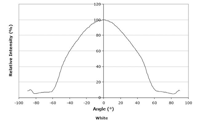
Examining the datasheet (http://www.cree.com/products/pdf/XLamp7090XR-E.pdf), and referring to page 5, we see:
[www.cree.com]
You can see that most of the power is contained within 120 degrees, and is actually not a horrible distribution - although it is still very directional. Past 60 degrees to each side, and there is virtually no signal power. I believe that this will actually be a good thing. It means that the light will not be 'escaping' to the sides (eliminating the need for a reflector on the side). This does, however means that it is likely that I will need to use a positioning of mounting to disperse more or less evenly.
I believe the resistor mostly acts as a protection component for the circuit (to disallow runaway voltages across the LED's - the controller also has a built-in overvoltage protection). at 33V and 100 mOhm, you only see a power consumption of 100mW across this resistor. I'm not sure what I will use for that resistor. The standard carbon resistors that are commonly used will not be adequate for that. As for current limiting, I'm not really versed well enough in the chip to tell you, but I don't believe that it is really used for current limiting - at the current this circuit is running at, it would be like stopping a steamroller with a pancake.
I hope this clears up things a bit.
Thank you,
-Peter L.
Peter,
You have wealth of knowledge on these things.
For high current capacity resistor, you may opt for wire-wound. I think the resistor for your application is the one with (normally white) ceramic covered resistor which can handle couple of ampheres.
If I can recall, the LED works like a diode, it will pick up a fixed operating voltage, whatever excess, the resistor partnering in series will take up the difference. The LED will then run at a current that is equal to the resistor. Let's say:
LED operating voltage = 1.6V
Resistor = 50 ohms
Voltage supplied across them = 3.0V
Resistor current = (3.0-1.6) / 50 = 28 mA = LED current.
Hi Freddy,
Yes, that is essentially how it works (LED means Light Emitting Diode). If you have ever looked at the operating conditions of a diode, examine this please:
What you can see is that at a bit of forward voltage, the diode turns on - this is what we expect. But as you increase the voltage just a bit, you have this large increase of current (the slope). This means, that if you directly connect a diode to an ideal voltage source, you must always maintain an accurate voltage, or you will try to drive a large amount of current through your diode - bad idea!
A wire wound resistor is what I am thinking of, since that will also be able to take a large amount of switching (especially in high power systems, even the large carbon resistors have physical cracking limits. Wire wound resistors are far more durable).
The problem with consideration of a 50 ohm resistor is that a typical resistor can only take .25 watts (a quarter watt resistor) continuously, and even then has thermal problems. If we solve:
P = I^2 * R
.25W = I^2 * 50
I = .070 A
I = 70 mA
Good current for a 20mA diode, but not a high current resistor (this is a carbon resistor generally). You are indeed correct in your logic though, and that is why the resistor there is commonly referred to as a 'protection resistor.' It will dissipate off that extra voltage - however it must be paid attention to that LED voltages do change depending on your current.
Also, on a design note, resistors are actually often not so desirable to have large currents. The only way that a resistor consumes power is by dissipating it into heat - nothing useful. This means, that you are getting losses in your circuit. Inveitably, there are losses - but the more you can transfer to what you actually want (meaning, the less you lose in the resistor), the better. It also means that we have less heat that we need to cool off from the system :P.
Our semi-ideal model would say that:
Diode off: open circuit
Diode on: 1.5V drop
In reality, this is not true; we use it as an approximation to simplify things and make ourselves feel better. Diodes actually will change their characteristics, being semiconductors, and do not have a fixed forward voltage. It makes more sense to consider a slightly more complex model of the diode, since we are dealing with a semiconductor which changes I-V characteristics.
A fairly standard one:
I_diode = I_saturation[exp([Q*V_d]/[nkT]) -1]
I_diode = I_saturation[exp([V_diode]/[nV_t]) - 1]
Where we consider the I_saturation (reverse) of the diode, V_diode will be the forward voltage, n is the nonideality factor, and V_t is the thermal voltage. I'm sorry, it is probably difficult to read those equations. If need be, I will scan in an image to post, which will make it more clear.
Thank you,
-Peter L.
Right, that is what I observed when I experiment with LED, it gets brighter as a result. I did not have a current meter to confirm that because I was young then and probably could not afford one.
At that time (late 70s), knowing that LEDs have low consumption and almost unlimited lifespan, I apply them on:
1) aquarium
I sink both battery and LED in aquarium. Silly but given limited brightness and the desire to create coloured lights effect near the ground, that is the way to go.
2) bicycle back warning light
I drill the back reflector with holes to sink in the LED.
I used the brake calipers movement as mechanical switch to switch on/off the light.

Hi Peter,
I am interseted in your project. Do you think you can share your whole porject info with us. Such as you did you get 33V 1A for your source? What is the best PWM frequency for aquarium or lighting and how do you achieve the frequency that you want. I also saw Osram have the Dragon LED which used around 300mA at 2.7V, what do you think? As for LED white colour usually used blue raw with yellow converter, the frequency will be out for plants, how do you overcome this?
Regards
Lam CT
Hi Lam,
You are right now seeing most of my project information. As I said, it is preliminary work right now. 33V at 1A is not difficult to produce on many power supplies, however you do need to ensure that it is a supply that is rated to handle that much current.
The PWM frequency will most directly impact the average power of the system. If you are running, say, a 50% duty cycle with a 40W handling, then for 50% of the time you have 40W, and 50% of the time you have 0 watts (neglect discharge time constants here). Averaging that would mean:
40W*t + 0W*t / 2t = 20W average
It is not quite that, as charging and discharging take a small amount of time. For frequency selection, it will depend on the frequency that you are driving the LED's at. I have not selected my frequencies yet, however I only plan to run them at a few kilohertz right now.
I am not familiar with the Osram or Dragon LED's, so I would need to see more information on them before I can answer anything to them. I had considered 300mA LED's for usage, but consider that a typical driver can support no more than 8 LED's in series (loading problem I think). This means that to deliver an equivalent power, you must have more channels of LED's, meaning more hardware (drivers, more LED's). I have not committed to using the very high power LED's, but at this point I think that they are more feasible to deal with.
I am still working on the frequency spectrum of emission. Primarily, as I understand, I need a high rejection of the green frequencies. A blue raw/yellow converter will definitely not work for this, but I have not closely checked specifications on some of the devices yet - I will not have time for a couple of months.
Thank you,
-Peter L.
Hi Peter,
did you calculate, that one LED has just an output of ca. 100 LM (to meet 50k working hours)?
I'm driving a 63l (16,6 gal) AQ with 2 x Dulux L 36W with in total 5600 LM and dimming the output to 75%. You're talking about 20 gal tanks and more, so it should fit anyhow.
This means that you need ca. 56 LEDs à 10-15 USD, w/o any controller, etc. Don't you think that your project will become too expensive, comparing with traditional lighting?
But if I'm wrong, it would be a very interesting project.
Regards Uwe
Hi Uwe,
I am not familiar with all the terms you are using, so my answer will be in pieces. From the data sheets I am using, it states a minimum lifetime of 50,000 hours per LED (but does not state frequency drift). For now, I think most of the application will be in high power lighting systems (such as coral tanks), where I have seen people using upwards of 800W of power, much of it from halide lighting.
When you say 100LM, what are you referring to by 'LM?'
For parts, right now I am working on getting them donated for at least the initial run. I will be working this summer at a semiconductor company that designs and manufactures the controllers I need, and they partner with one of the big power LED companies. I have not priced the LEDs yet, but will be doing so over the summer.
Assuming that we have almost entirely power transferral, you get about 4W per LED (not quite right, but let us assume that for now). To match your lighting, I would need 18 LED's. The story does not quite end there though. Unlike traditional lighting (incandescent, fluorescent, halid), LED's are highly directional light sources. A typical viewing angle is 120 degrees, which is a two edged sword. One of the benefits is that you can really point the light in the direction of a tank, unlike a fluorescent bulb where it quite literally just goes everywhere (this is why reflectors are used). However, it does lend problems to even lighting, which I am still working on.
I would expect this to be more useful in the high power regions though, especially in situations where heat has become a problem (I abhorr the halide lighting systems!). Probably not so much in the 'low end' aquariums for average use, just growing a couple plants.
Thank you,
-Peter L.
Hi Peter,
LM (lm) stands for Lumen as unit of the http://en.wikipedia.org/wiki/Luminous_flux. I used the capitals version to avoid confusion.
This means the effective quantity of light, that can be used by plants. The wattage is just the quantity of power that is needed to produce this output.
For T8/T5 flourescent tubes the rule of thumb (0,5-1 W per litre) fits the requirements of the most of plants.
The specs of the Luxeon K2 shows us ~100 LM at 1000 mA, but I didn't found a word about the power consumtion. I understood that it is 4-5 W, than it is not really an energy effective device.
Reference: http://www.luxeon.com/pdfs/DS51.pdf
Anyway with 18 LEDs you'll produce only ±1.8k LM equal to a single T8 18 W tube (maybe more effectiv, because of the spotlight design), but for a multiple of the price.
To be discussed is the matter if the colour spectrum or the frequency fits most to higher plants or to algae.
The price assumption had been a result of a quick search at xbay, I found 9 to 20 Euro, w/o looking to any specifications.
Regards Uwe
Edit: Ok, you are talking about this generation of LEDs: http://www.osram.com/appscom/cgi-bin...chiv.pl?id=532
I now understand the rapture, 1000 LM is a a little more than the specs that I found before. From this one you will need less than 18 pieces.
Apology, if I troubled by fault. Uwe
Hi Uwen,
Sorry, I have been very busy with finals, and I am at my new job - which is generally 11-12 hours a day. I will take some time to read over the links you have posted, and search the datasheets for the information I will need. I'll respond when I have some time - I just didn't want you thinking I'd fallen off the face of the Earth :P
Thank you,
-Peter L.
 Posting Permissions


Bookmarks